Current, voltage and power
ACS712 current sensor with ESP32
The ACS712 is a 5 V analog part, and that makes it awkward on an ESP32. Its output sits at half the supply, about 2.5 V at zero current, and swings up or down with current direction. That can reach beyond what an ESP32 pin accepts, so a voltage divider is required. With 10 kΩ from the output to the pin and 18 kΩ from the pin to ground, the ratio is about 0.643: a zero-current output of 2.5 V becomes about 1.61 V, and the 30 A version stays within about 0.33 to 2.88 V.
Three versions look alike, so read the marking on the chip: 185 mV per amp for 5 A, 100 mV per amp for 20 A, and 66 mV per amp for 30 A. Using the wrong value in code gives a neat, wrong number. The output is ratiometric, so any change in the 5 V supply moves the reading too. Measure the zero point with no load instead of assuming 2.5 V. The example does that at start-up, so start it with the load off.
Precision is limited. At 66 mV per amp, a small current is lost in ADC noise, and the ESP32 ADC is not linear. Averaging helps. For small DC currents, an INA219 or INA226 does better. Where the ACS712 fits is higher current and isolation: the sensing path is separate from the output side. On AC, the output is a wave around the zero point, so a single sample means nothing and you need to sample a whole cycle. LCD Ultra Pro can read an analog pin and scale it for a bar without code.
Specifications
| Supply | 5 V |
|---|---|
| Zero-current output | Supply / 2, about 2.5 V |
| 5 A version | 185 mV/A |
| 20 A version | 100 mV/A |
| 30 A version | 66 mV/A |
| Example divider | 10 kΩ + 18 kΩ, ratio 0.643 |
Power and logic levels
5 V signal: needs a divider or level shifter
| Supply | 5 V |
|---|---|
| Signal level | Output up to about 5 V |
| On an ESP32 | Use a divider on OUT. Never connect it straight to a GPIO. |
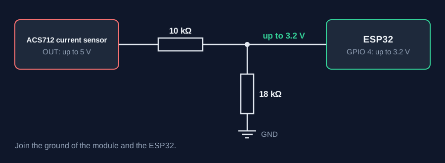
ESP32 pins, including those on a display board's connectors, work at 3.3 V and are not 5 V tolerant. Modules differ, so if in doubt, measure the signal before you connect it.
Wiring
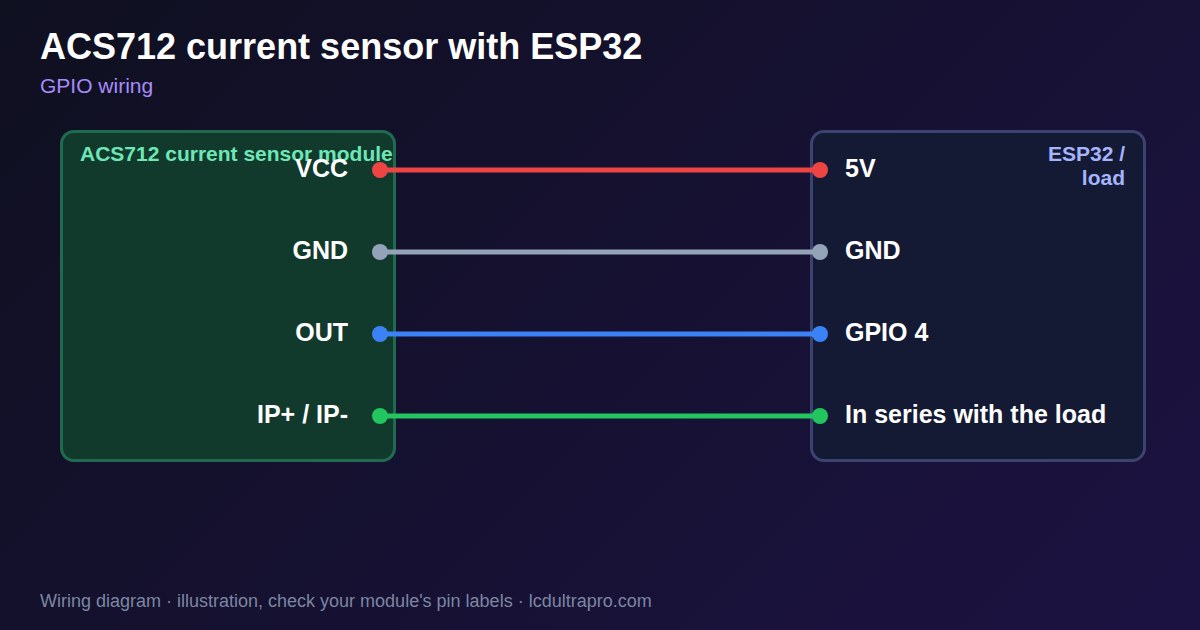
| ACS712 current sensor | Connect to | Note |
|---|---|---|
| VCC | 5V | |
| GND | GND | |
| OUT | GPIO 4 | Through 10 kΩ, with 18 kΩ to GND |
| IP+ / IP- | In series with the load | Fuse the circuit |
Arduino code
const int OUT_PIN = 4;
const float RATIO = 18.0 / (10.0 + 18.0);
const float MV_PER_AMP = 185.0;       // 100 or 66 on other versions
float zeroMv;

float readMv() {                      // average to reduce ADC noise
  long sum = 0;
  for (int i = 0; i < 200; i++) sum += analogReadMilliVolts(OUT_PIN);
  return sum / 200.0 / RATIO;
}

void setup() {
  Serial.begin(115200);
  zeroMv = readMv();                  // load must be off at boot
}

void loop() {
  Serial.printf("%.2f A\n", (readMv() - zeroMv) / MV_PER_AMP);
  delay(500);
}
No extra library needed. Compiled for ESP32-S3 with arduino-esp32 3.x. Not yet tested by us on a physical sensor. Change the pins to match your board.
On a display
In LCD Ultra Pro a rule can read an analog pin and scale it for a bar or label.
Design a display for ACS712 current sensorBoards with a ready connector
Only boards whose connectors we have surveyed. Others may still work on free GPIOs.
| Elecrow CrowPanel ESP32 HMI 2.4" | GPIO_D port: GPIO 32 (ADC) |
| Elecrow CrowPanel ESP32 HMI 2.8" | GPIO_D port: GPIO 32 (ADC) |
| Elecrow CrowPanel ESP32 HMI 3.5" | GPIO_D port: GPIO 32 (ADC) |
| LilyGO T-Display (classic) 1.14" | Right pin header: GPIO 36 (ADC)36 / 37 / 38 / 39 are input-only |
| M5Stack AtomS3 0.85" | Grove port: GPIO 2 (ADC) |
| M5Stack M5StickC Plus2 1.14" | Grove port: GPIO 32 (ADC) |
| Sunton ESP32-2432S028R 2.8" | GPIO header (P3): GPIO 35 (ADC)GPIO 21 is the display backlight — not usable. GPIO 35 is input-only. No 3V3 pin on P3 (only GND). |
| Waveshare ESP32-S3-LCD-7B | GPIO connector (J8): GPIO 6 (ADC) |
Good to know
- The output needs a divider on an ESP32.
- Check which of the three versions you have.
- Measure the zero point yourself.
- It is weak at small currents.
What it is good for
- Motor and load current
- Higher current DC monitoring
- Detecting that a device is running
FAQ
Can I connect ACS712 output directly to an ESP32?
No. Use a voltage divider, because the output can exceed the pin's range.
Why do I read current with nothing connected?
The zero point differs from 2.5 V. Measure it with no load.
Can it run from 3.3 V?
It is a 5 V part, so power it from 5 V and use a divider.
Sources
Related parts
Use this information at your own risk. It is for general guidance only: the example code compiles, but it has not been tested on every part, and modules differ between sellers. Check the manufacturer's data before you build. Product names belong to their owners, and LCD Ultra Pro is not affiliated with them. See our Terms.