Motors
BTS7960 motor driver with ESP32
The 43 A printed on BTS7960 listings is not what you get from the small module on a typical bench. Treat it as an upper bound under ideal cooling. Blogs repeat the number, and one claims no extra cooling is needed, but no independent thermal test turned up in our sources. So measure the temperature under real load, and expect much less, especially when a motor stalls.
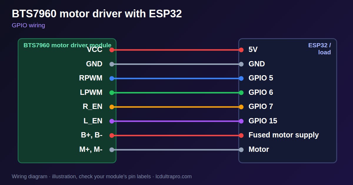
This is the step up from a TB6612FNG, for motors of several amps on a 12 V or 24 V supply. Listings give 6 to 27 V on the motor side. The motor supply goes to B+ and B-, and VCC is a separate 5 V logic supply. The grounds have to be joined. A forum thread quotes a 2.15 V input threshold for the chip, and sellers list 3.3 V logic, but the board has a buffer in front of it, so test yours and fit a level shifter if it is unreliable. Always put a fuse in the battery line, since these supplies can deliver enough current to start a fire.
Control takes four pins: R_EN and L_EN enable each half-bridge, and RPWM and LPWM set speed in each direction. Send PWM to one and hold the other low. Never drive both high: the guides warn this may damage the module. A motor's stall current can be many times its running current, so size the fuse with that in mind. Keep motor wires away from the display cable, because they radiate noise, and take the 5 V for logic from a clean source. The IS pins report current at a nominal ratio of 8500:1, which is about 0.12 V per amp across 1 kΩ. In a fault they jump higher, and one user reports up to 7 V, so divide IS before it reaches a GPIO. Four GPIOs is a lot on a parallel RGB board. LCD Ultra Pro can set a PWM pin from a slider or rule.
Specifications
| Motor supply | 6–27 V |
|---|---|
| Logic supply | 5 V (VCC) |
| Listed current | 43 A, plan for much less |
| Control | RPWM, LPWM, R_EN, L_EN |
| Current sense | IS pins, scale per datasheet |
Power and logic levels
3.3 V: check your module first
| Supply | VCC listed as 3.3–5 V or 5 V, motor 6–27 V |
|---|---|
| Signal level | Inputs usually work at 3.3 V. IS can reach several volts in a fault |
| On an ESP32 | Test your module, or fit a level shifter. Divide IS before it reaches a GPIO. |
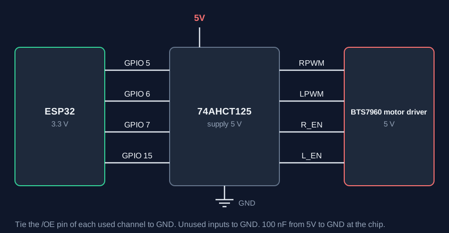
ESP32 pins, including those on a display board's connectors, work at 3.3 V and are not 5 V tolerant. Modules differ, so if in doubt, measure the signal before you connect it.
Wiring
| BTS7960 motor driver | Connect to | Note |
|---|---|---|
| VCC | 5V | Logic supply |
| GND | GND | Common with motor supply |
| RPWM | GPIO 5 | |
| LPWM | GPIO 6 | |
| R_EN | GPIO 7 | |
| L_EN | GPIO 15 | |
| B+, B- | Fused motor supply | |
| M+, M- | Motor |
Arduino code
const int RPWM = 5, LPWM = 6, R_EN = 7, L_EN = 15;
const int FREQ = 5000, BITS = 10;

void motor(int speed) {               // -1023 to 1023
  ledcWrite(speed > 0 ? LPWM : RPWM, 0);     // never both at once
  ledcWrite(speed > 0 ? RPWM : LPWM, abs(speed));
}

void setup() {
  pinMode(R_EN, OUTPUT);
  pinMode(L_EN, OUTPUT);
  ledcAttach(RPWM, FREQ, BITS);
  ledcAttach(LPWM, FREQ, BITS);
  digitalWrite(R_EN, HIGH);
  digitalWrite(L_EN, HIGH);
}

void loop() {                         // ramp, do not jump
  for (int s = 0; s <= 600; s += 10) { motor(s); delay(20); }
  delay(2000);
  for (int s = 600; s >= 0; s -= 10) { motor(s); delay(20); }
  delay(2000);
}
No extra library needed. Compiled for ESP32-S3 with arduino-esp32 3.x. Not yet tested by us on a physical sensor. Change the pins to match your board.
On a display
Read the value in your sketch and pass it to a label, or send it over MQTT and show it with an MQTT value in the editor.
Design a display for BTS7960 motor driverBoards with a ready connector
Only boards whose connectors we have surveyed. Others may still work on free GPIOs.
| LilyGO T-Display (classic) 1.14" | Left pin header: GPIO 21, 22, 17, 13 |
| M5Stack AtomS3 0.85" | Bottom pin header: GPIO 5, 6, 7, 8 |
| Waveshare ESP32-S3 Touch LCD 1.28" round | SH1.0 GPIO header: GPIO 15, 16, 17, 18Six GPIOs led out per the wiki pin table |
| Waveshare ESP32-S3 Touch LCD 1.28" round (CNC metal housing) | SH1.0 GPIO header: GPIO 15, 16, 17, 18Six GPIOs led out per the wiki pin table |
Good to know
- 43 A is an upper bound. Measure the heat.
- Never drive both PWM inputs high.
- Fuse the motor supply.
- Check 3.3 V logic on your module.
What it is good for
- Large DC motors
- Actuators and winches
- Electric vehicles and carts
FAQ
Can a BTS7960 really handle 43 A?
Treat that as a limit under ideal cooling. Plan for much less.
Does it work with 3.3 V logic?
Reports and sellers say usually yes, but boards differ. Test yours, or use a level shifter.
What happens if both PWM inputs are high?
Guides warn it may damage the module. Keep one low.
Sources
- https://docs.cirkitdesigner.com/component/d7d3f050-2543-47b2-872e-dab4f5f1d532/bts7960-ibt-2-motor-driver
- https://www.digikey.ie/en/maker/projects/control-powerful-electric-skateboard-e-bike-350w-dc-motor-using-arduino/08eb1badacfc487aa6b50a04cbada7cb
- https://forum.arduino.cc/t/bts7960-btn7960n-ibt-2-motor-drive-module/1142926
Related parts
Use this information at your own risk. It is for general guidance only: the example code compiles, but it has not been tested on every part, and modules differ between sellers. Check the manufacturer's data before you build. Product names belong to their owners, and LCD Ultra Pro is not affiliated with them. See our Terms.