Input devices
MCP23017 GPIO expander with ESP32
Running out of pins is the usual problem on a parallel RGB display, where the panel takes most of them. An MCP23017 gives you 16 digital pins from two I2C wires, so one spare connector can run a set of relays or a 4x4 keypad. Up to eight fit on one bus with addresses 0x20 to 0x27, selected by pins A0, A1 and A2.
Old tutorials will mislead you on one point. Microchip's current datasheet lists GPA7 and GPB7 as output only on this chip, since using them as inputs can corrupt the SDA line under some conditions. The notice says the datasheet changed and the silicon did not. So many tutorials still use all 16 as inputs, and some people report no trouble, while others have had a whole bus lock up. Plan on 14 inputs at most. Keep those two pins for outputs.
Tie RESET high through a resistor or directly: it is active low, and a floating RESET causes random restarts of the chip. Do the same for A0, A1 and A2, which must not float. Pins are slower than native GPIOs and go through an I2C transfer, so this is no use for PWM, step pulses or WS2812 data. Inputs can use internal pull-ups, enabled in a register, and the INTA and INTB pins can tell the ESP32 when something changed, so you do not need to poll. The chip's pins cannot drive relay coils directly. Keep to the same drive limits as any logic output. The example turns on one output and reads a button with no library.
Specifications
| Extra pins | 16 (GPA7, GPB7 output only) |
|---|---|
| Interface | I2C |
| I2C address | 0x20 to 0x27 by A0–A2 |
| Devices per bus | Up to 8 |
| RESET | Active low, tie high |
| Interrupt outputs | INTA, INTB |
Power and logic levels
3.3 V: safe to connect directly
| Supply | 1.8–5.5 V, use 3V3 |
|---|---|
| Signal level | I2C and all 16 pins follow the supply |
| On an ESP32 | Run it from 3V3. At 5 V, every pin becomes a 5 V pin. |
ESP32 pins, including those on a display board's connectors, work at 3.3 V and are not 5 V tolerant. Modules differ, so if in doubt, measure the signal before you connect it.
Wiring
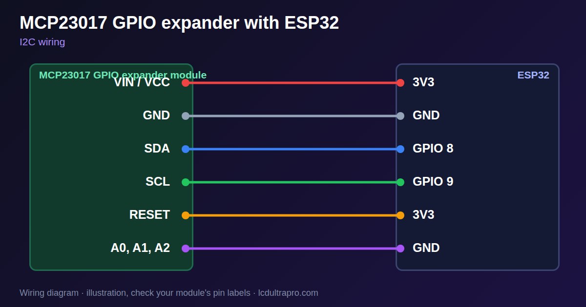
| MCP23017 GPIO expander | Connect to | Note |
|---|---|---|
| VIN / VCC | 3V3 | |
| GND | GND | |
| SDA | GPIO 8 | Any free pin, set in Wire.begin() |
| SCL | GPIO 9 | Any free pin, set in Wire.begin() |
| RESET | 3V3 | Must not float |
| A0, A1, A2 | GND | Address 0x20 |
Arduino code
#include <Wire.h>

const int SDA_PIN = 8, SCL_PIN = 9;
const uint8_t ADDR = 0x20;

void writeReg(uint8_t reg, uint8_t value) {
  Wire.beginTransmission(ADDR);
  Wire.write(reg); Wire.write(value);
  Wire.endTransmission();
}

uint8_t readReg(uint8_t reg) {
  Wire.beginTransmission(ADDR);
  Wire.write(reg);
  Wire.endTransmission();
  Wire.requestFrom(ADDR, (uint8_t)1);
  return Wire.read();
}

void setup() {
  Serial.begin(115200);
  Wire.begin(SDA_PIN, SCL_PIN);
  writeReg(0x00, 0x00);               // port A: all outputs
  writeReg(0x01, 0x7F);               // port B: inputs, GPB7 output
  writeReg(0x0D, 0x7F);               // port B pull-ups
}

void loop() {
  bool pressed = !(readReg(0x13) & 0x01);   // button on GPB0 to GND
  writeReg(0x14, pressed ? 0x01 : 0x00);    // LED on GPA0
  delay(20);
}
No extra library needed. Compiled for ESP32-S3 with arduino-esp32 3.x. Not yet tested by us on a physical sensor. Change the pins to match your board.
On a display
Read the value in your sketch and pass it to a label, or send it over MQTT and show it with an MQTT value in the editor.
Design a display for MCP23017 GPIO expanderBoards with a ready connector
Only boards whose connectors we have surveyed. Others may still work on free GPIOs.
| Elecrow CrowPanel ESP32 HMI 2.4" | I2C port: SDA 22, SCL 21Not shared with the touch controller (it is on SPI) — free for sensors |
| Elecrow CrowPanel ESP32 HMI 2.8" | I2C port: SDA 22, SCL 21Not shared with the touch controller (it is on SPI) — free for sensors |
| Elecrow CrowPanel ESP32 HMI 3.5" | I2C port: SDA 22, SCL 21Not shared with the touch controller (it is on SPI) — free for sensors |
| Elecrow CrowPanel ESP32-S3 HMI 5.0" | I2C port: SDA 19, SCL 20Same I2C bus as the GT911 touch (0x14 / 0x5D) and, on V3.0 boards, the PCA9557 touch-reset expander (0x18) |
| Elecrow CrowPanel ESP32-S3 HMI 7.0" | I2C port: SDA 19, SCL 20Same I2C bus as the GT911 touch (0x14 / 0x5D) and, on V3.0 boards, the PCA9557 touch-reset expander (0x18) |
| LilyGO T-Display-S3-Pro 2.33" | QWIIC RIGHT: SDA 5, SCL 6I2C only — same bus as the touch, the PMU (SY6970) and the light sensor |
| M5Stack AtomS3 0.85" | Bottom I2C pins: SDA 38, SCL 39Same I2C bus as the built-in IMU (MPU6886, 0x68) |
| Makerfabs MaTouch ESP32-S3 Rotary IPS 2.1 Round | Mabee I2C (J1): SDA 17, SCL 18Same I2C bus as the touch controller (CST826) |
| Makerfabs MaTouch ESP32-S3 Parallel TFT 4.3" | Mabee I2C: SDA 17, SCL 18Same I2C bus as the touch controller (GT911) |
| Makerfabs MaTouch ESP32-S3 Parallel TFT with Touch 5.0" | Mabee I2C: SDA 17, SCL 18Same I2C bus as the touch controller (GT911) |
| Makerfabs MaTouch ESP32-S3 Parallel TFT with Touch 7.0" | Mabee I2C: SDA 17, SCL 18Same I2C bus as the touch controller (GT911) |
| Sunton ESP32-4827S043R/C 4.3" | I2C header (P3): SDA 19, SCL 20Same I2C bus as the GT911 touch controller. P3 also carries GPIO 17 / 18. |
| Sunton ESP32-8048S043C 4.3" | I2C header (P3): SDA 19, SCL 20Same I2C bus as the GT911 touch controller. P3 also carries GPIO 17 / 18. |
| Sunton ESP32-8048S050C 5.0" | I2C header (P3): SDA 19, SCL 20Same I2C bus as the GT911 touch controller. P3 also carries GPIO 17 / 18. |
| Sunton ESP32-8048S070C 7.0" | I2C header (P3): SDA 19, SCL 20Same I2C bus as the GT911 touch controller. P3 also carries GPIO 17 / 18. |
| Waveshare ESP32-S3 Touch LCD 2.1" round | I2C connector: SDA 15, SCL 7Same I2C bus as the touch controller, the IO expander, the RTC and the IMU (addresses 0x15/0x5D, 0x20, 0x51, 0x6B, 0x7E taken) |
| Waveshare ESP32-S3 Touch LCD 2.8" | I2C connector: SDA 11, SCL 10Same I2C bus as the RTC and the IMU (0x51, 0x6B, 0x7E taken) — the touch has its own bus |
| Waveshare ESP32-S3 Touch LCD 2.8" Type B | I2C connector: SDA 15, SCL 7Same I2C bus as the touch controller, the IO expander, the RTC and the IMU (addresses 0x15/0x5D, 0x20, 0x51, 0x6B, 0x7E taken) |
| Waveshare ESP32-S3-Touch-LCD-2.8C | I2C connector: SDA 15, SCL 7Same I2C bus as the touch controller, the IO expander, the RTC and the IMU (addresses 0x15/0x5D, 0x20, 0x51, 0x6B, 0x7E taken) |
| Waveshare ESP32-S3-LCD-7B | I2C connector (H1): SDA 8, SCL 9Same I2C bus as the touch controller (GT911) and the IO expander (CH422G) |
Good to know
- GPA7 and GPB7 are output only.
- Do not leave RESET or address pins floating.
- Too slow for PWM or LED strip data.
- Scan first: other chips may use the same address.
What it is good for
- Boards short of GPIO
- Banks of relays and buttons
- 4x4 keypads on two wires
FAQ
Can GPA7 be an input on the MCP23017?
Microchip's current datasheet says no: GPA7 and GPB7 are output only.
How many can I connect?
Up to eight, addresses 0x20 to 0x27.
Can it do PWM?
No. Use a PCA9685 for that.
Sources
Related parts
Use this information at your own risk. It is for general guidance only: the example code compiles, but it has not been tested on every part, and modules differ between sellers. Check the manufacturer's data before you build. Product names belong to their owners, and LCD Ultra Pro is not affiliated with them. See our Terms.