Which pin
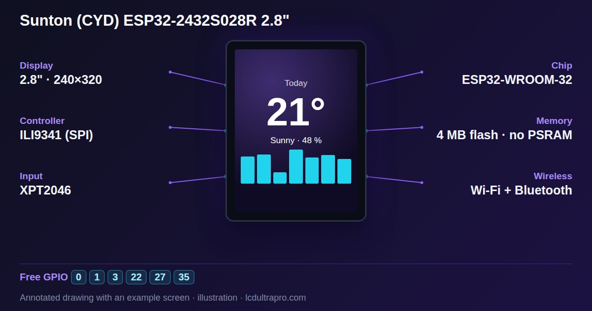
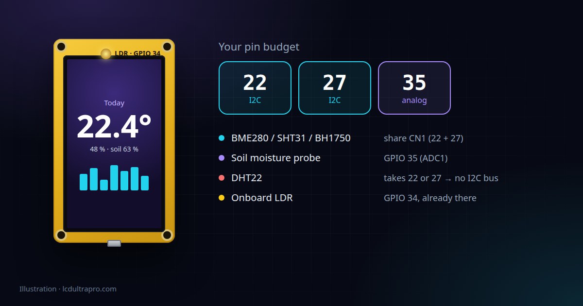
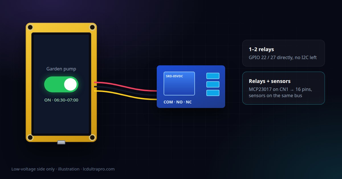
Only GPIO 22 and 27 can drive an output, both on the CN1 connector. GPIO 35 is input-only and won't switch anything. So a relay goes on 27 or 22, and that has a cost: those two pins are also your only I2C bus. Use one of them for a relay and the I2C sensors you might have added are off the table.
That gives you two sensible layouts. One or two relays and no I2C sensors: wire the relays straight to 22 and 27. Relays and sensors: keep 22 and 27 as I2C and put the relays behind an expander on that bus. More on that below.
The 3.3 V problem
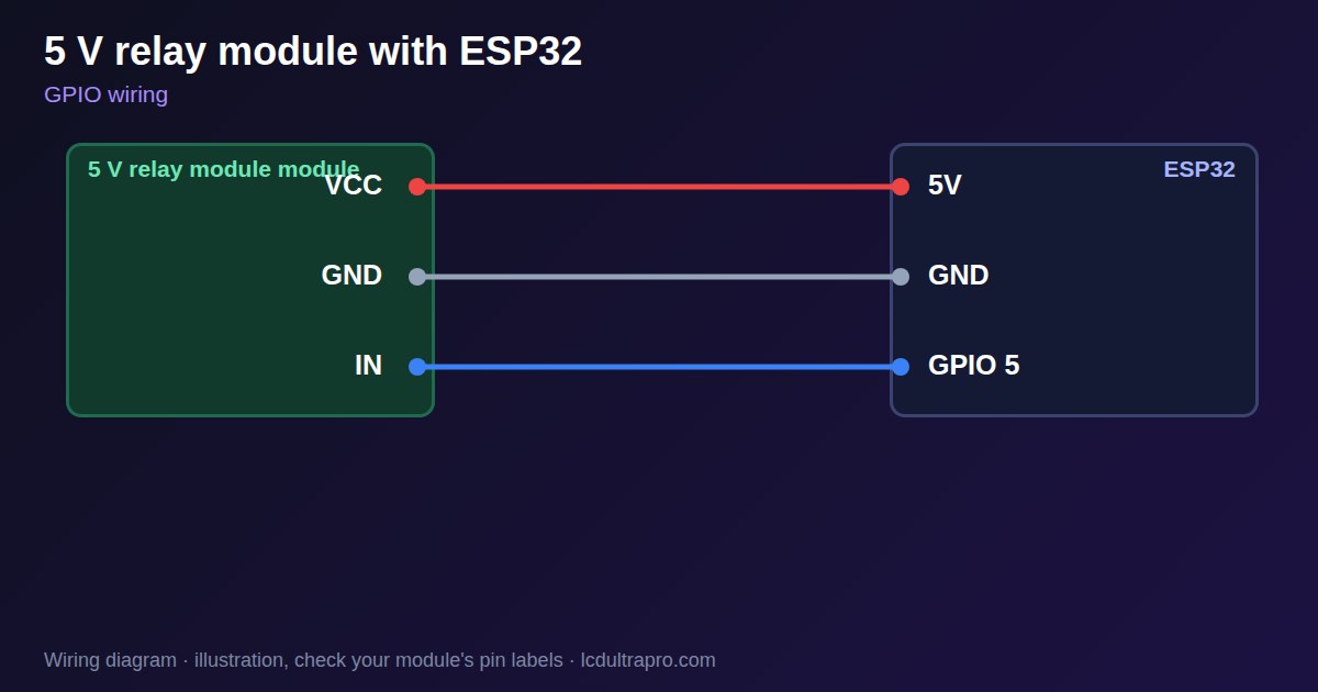
Most cheap relay modules are built for 5 V. The coil needs 5 V to pull in, and the input side often expects a 5 V signal too. The ESP32's pins give 3.3 V, and with some modules that's not quite enough to switch them off reliably. The relay clicks on fine and then won't let go.
Modules with a JD-VCC jumper solve it neatly. Remove the jumper, feed the coil from 5 V on JD-VCC, and connect VCC on the input side to the CYD's 3.3 V. Now the input works at 3.3 V logic and the coil still gets its 5 V. Modules without that jumper need a small NPN transistor between the GPIO and the relay input. Our relay module page has both circuits drawn out.
Most modules are active-low, meaning the relay turns on when the pin goes low. Check yours, because it changes what "on" means in your code.
The click at boot
Plug the CYD in and the relay may click once before your sketch even starts. While the ESP32 boots, its pins aren't driven yet, and an active-low module can read that as "on" for a moment. For a lamp it doesn't matter. For a pump or a heater it might. In your code, write the off level to the pin before you set it as an output, and the click mostly goes away.
const int RELAY = 27;

void setup() {
  digitalWrite(RELAY, HIGH);   // off for an active-low module
  pinMode(RELAY, OUTPUT);
}
More than two relays
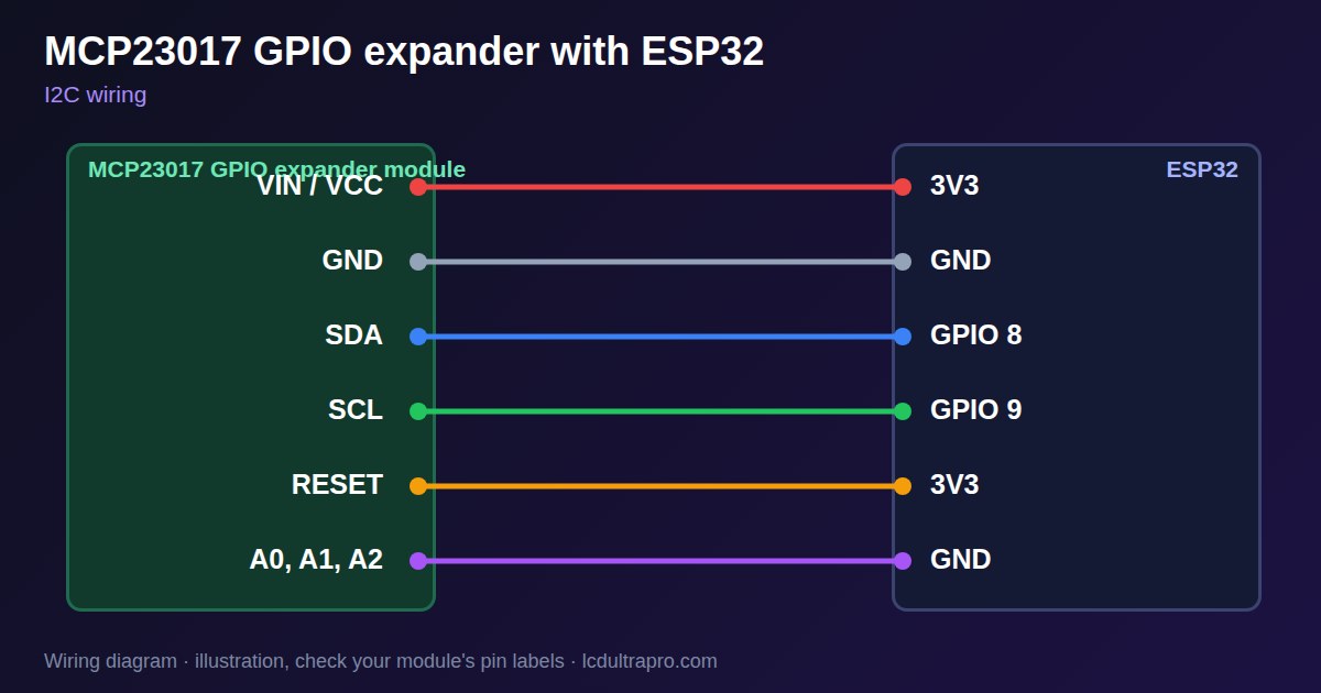
An MCP23017 on CN1 gives you sixteen digital pins over I2C, and your temperature sensor can sit on the same two wires. It's the right move if the project will ever grow. Run it from 3.3 V, tie its address and reset pins to something rather than leaving them floating, and note that two of its pins, GPA7 and GPB7, can only be outputs on this chip.
To be upfront about the editor side: in LCD Ultra Pro, a relay on a CYD pin is switched straight from a button or a rule with no code. Driving relays through an MCP23017 needs a few lines of your own code in the custom code window. It's not hard, but it isn't a click-and-done feature.
Switching on a schedule
A relay that only switches when you tap the screen is half a project. The editor has two time components that fit the CYD: a time switch that runs your rules at a set time on chosen days, and an on/off timer with a start and an end, like 6:30 to 7:00 on weekdays. Both remember their settings after a power cut, and both need to know the time, either from the internet over Wi-Fi or set by hand. The weekly schedule screen with six time slots needs a 4 inch display, so it isn't offered on the CYD.
NO or NC
Last thing, and it's easy to get backwards. A relay has a normally open and a normally closed contact. Wire your load to NC and it's on whenever the relay is idle, which includes when the CYD is unplugged, crashed or rebooting. For heating or a pump, think about which state is safe when nothing is in control, and wire it so that's the default. For most loads, that's NO.
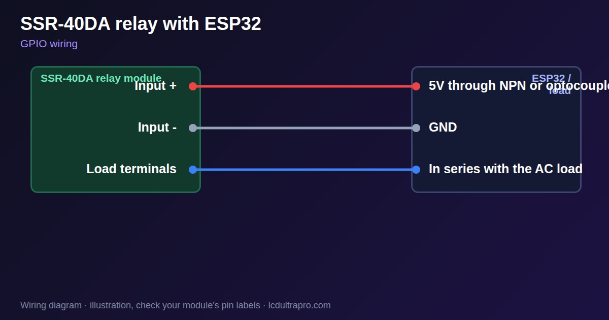
For loads that switch often, or mains loads where you'd rather avoid the click and contact wear, a solid state relay is worth a look. The SSR-40DA only switches AC and needs a heatsink, but it's silent and still takes a single GPIO.
- #cheap yellow display
- #relay
- #esp32 relay
- #mcp23017
- #home automation