Where the pins went
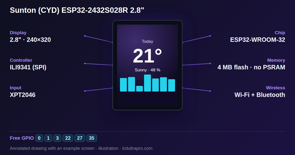
The ESP32-WROOM-32 on this board has more GPIOs than most hobby projects need. The CYD just spends almost all of them before you get a say.
The display runs on its own SPI bus. The XPT2046 touch controller gets a second, separate one. The microSD slot takes four pins, the RGB LED three, and the speaker amp and the light sensor one each. That's most of the board spoken for:
| GPIO | Taken by |
|---|---|
| 2, 12, 13, 14, 15 | Display: DC, MISO, MOSI, SCLK, CS |
| 21 | Display backlight (PWM, on = HIGH) |
| 25, 32, 33, 36, 39 | Touch: CLK, MOSI, CS, IRQ, MISO |
| 5, 18, 19, 23 | microSD: CS, SCK, MISO, MOSI |
| 4, 16, 17 | RGB LED: red, green, blue |
| 26 | Speaker amplifier (P4 connector) |
| 34 | Light sensor (LDR) |
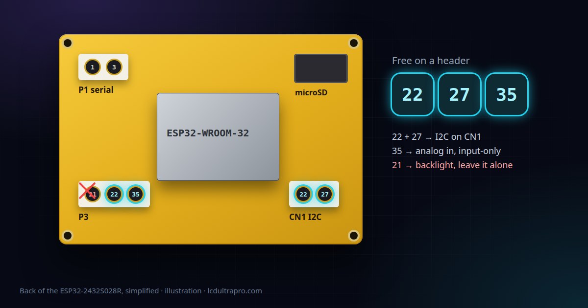
Apart from the speaker connector, only one of these shows up on a header. That's GPIO 21, and you shouldn't use it. More on that below.
GPIO 22, 27 and 35
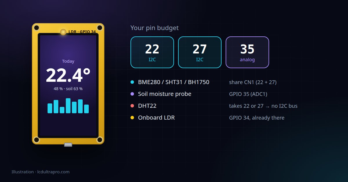
GPIO 27 sits on the CN1 connector. GPIO 22 is on CN1 too, and also on P3. That's one pin wired to two places, not two pins. Use it on either connector, just not for two things at once.
GPIO 35, on P3, is the odd one. It's input-only, so no LEDs or relays, and because it has no internal pull-up, a button needs an external resistor. Where it shines is analog input. It's on ADC1, and ADC1 keeps working with Wi-Fi on. The ADC2 pins on an ESP32 stop working as soon as the radio starts, which trips up a lot of people on other boards.
Two more pins look free and aren't really. GPIO 1 and 3 on P1 are the serial port, shared with the USB-to-serial chip, so anything you put there fights with uploads and the serial monitor. GPIO 0 is the BOOT button and doesn't reach a header at all.
The connectors
CN1 is the one you want. GPIO 22, GPIO 27, 3.3 V and ground. That's exactly what an I2C sensor needs, and nothing else on the board uses those pins.
P3 has GPIO 21, 22 and 35, plus ground but no 3.3 V, so a sensor on P3 has to borrow power from CN1. P1 is the serial port with 5 V on it. P4 is for the speaker.
Getting more out of two pins
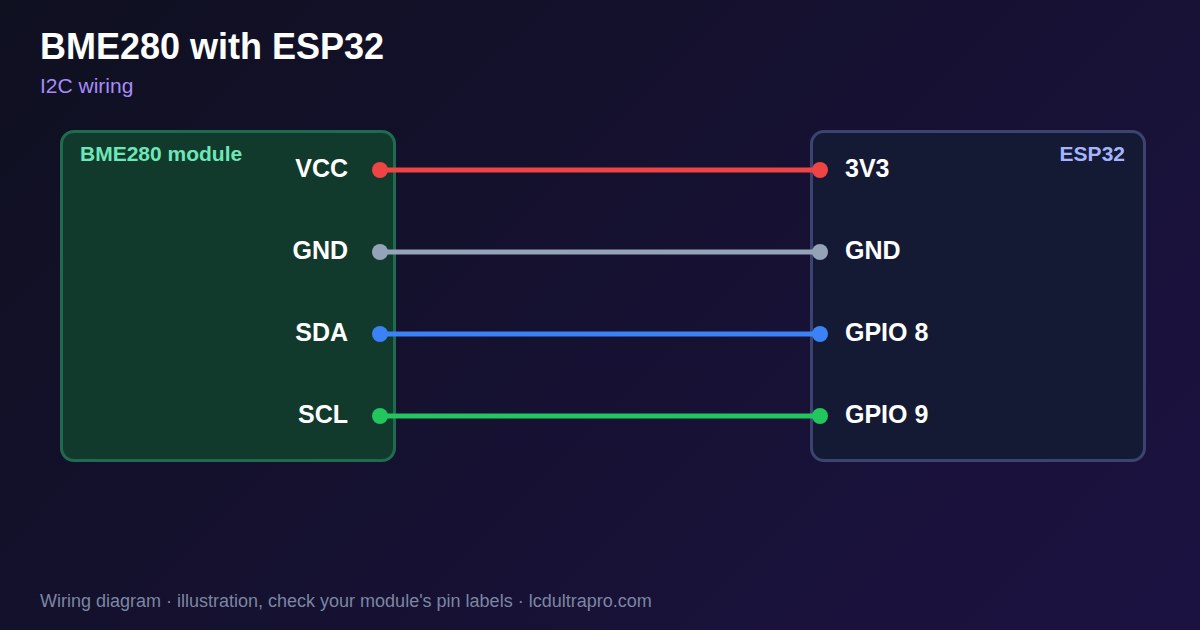
Two usable pins doesn't sound like much. But it's enough for I2C, and I2C can carry several sensors at once, as long as their addresses don't clash. A BME280 for temperature, humidity and pressure, a light sensor and an ADC module can all hang off CN1 together. Not sure about your mix? Run it through the I2C address checker before you order anything.
#include <Wire.h>

void setup() {
  Wire.begin(27, 22);   // SDA = GPIO 27, SCL = GPIO 22
}
The ESP32 doesn't care which one is SDA and which is SCL, so Wire.begin(22, 27) works too. It just has to match your wiring.
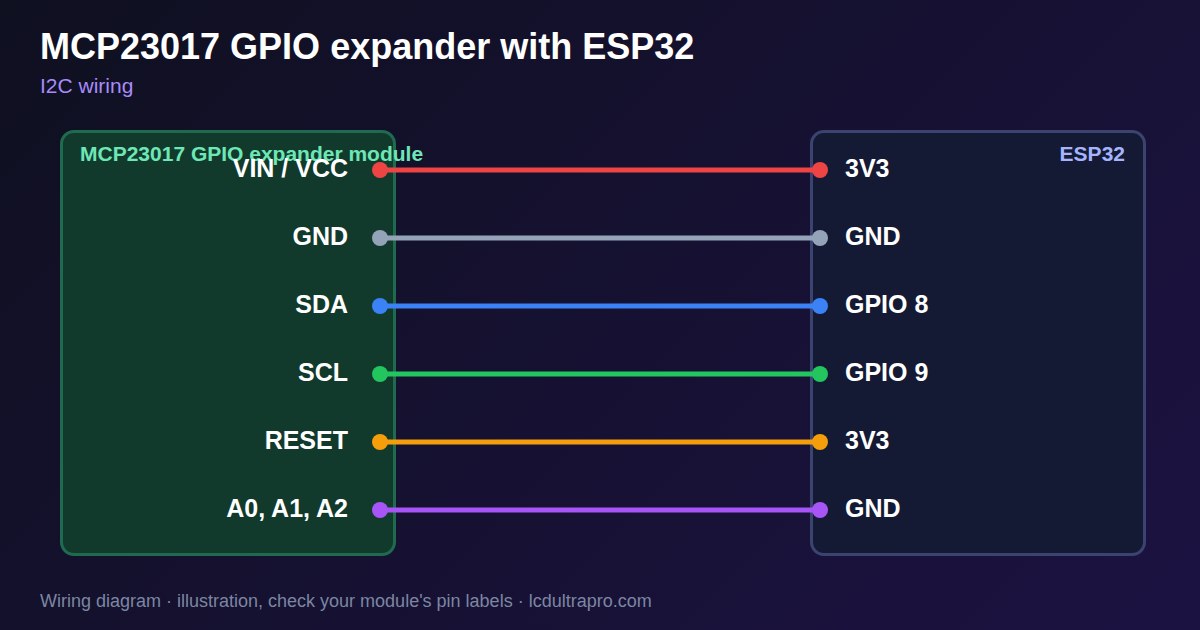
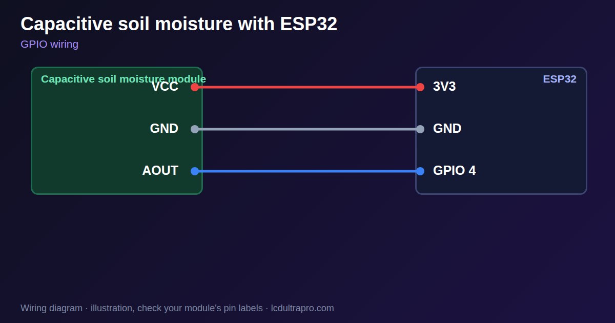
For outputs I'd put an MCP23017 on the same bus. Sixteen more digital pins, enough for a bank of relays or a row of buttons, and you never touch the board. That leaves GPIO 35 for one analog sensor, say a capacitive soil moisture probe or a pot.
What I wouldn't do
There are forum posts about soldering onto the SD slot to get GPIO 5, 18, 19 and 23 back when you don't use a card. It works. The pads are tiny, though, and GPIO 5 is a strapping pin that the chip reads at every reset. An expander module costs a few euros, so I wouldn't bother.
GPIO 1 and 3 are the other trap. A sensor there looks fine until the next upload, or until you open the serial monitor to find out why it stopped working.
And keep other devices off the touch bus. Touch gets flaky.
In the editor
If you build the UI in LCD Ultra Pro, pick the CYD when you create the project. The pin pickers in the event rules then only offer pins that actually reach its connectors, with the serial pins flagged as risky. Custom code gets a warning if it uses a pin that is not on that list, and the export checks again before it writes the sketch. The full pin map is on the ESP32-2432S028R board page.
Our pin data comes from the community reference in witnessmenow's ESP32-Cheap-Yellow-Display repository and the PlatformIO board definition by rzeldent, last checked on 27 October 2026.
My advice: go I2C
Still picking sensors for a CYD project? Take the I2C versions wherever you can. A DHT22 needs one of your two output-capable pins all to itself, and after that you no longer have a full I2C bus. An I2C temperature sensor shares the two wires with everything else and leaves GPIO 35 for the one thing that really has to be analog.
- #cheap yellow display
- #esp32-2432s028r
- #gpio
- #pinout
- #i2c