M5Stack · ESP32 · 1.14" · 135×240
M5Stack M5StickC Plus specifications
This page collects the pinout, free GPIOs and hardware details of the M5Stack M5StickC Plus. The board isn't in the LCD Ultra Pro™ editor yet, so there's no driver for it there.
The StickC Plus is the version of M5Stack's stick that most people mean when they say StickC. It's the size of a USB stick, 48 × 24 mm, with a 1.14-inch 135×240 screen, two buttons, an IR transmitter and a 120 mAh battery.
Under the case there's an ESP32-PICO-D4 with 4 MB of flash, an AXP192 power management chip, an MPU6886 IMU and a BM8563 clock, all on I2C at GPIO 21/22. The ST7789v2 display takes SPI on GPIO 13 (clock) and 15 (data), with DC 23, CS 5 and reset 18. A PDM microphone uses GPIO 0 and 34, and a passive buzzer sits on GPIO 2.
For your own parts there's a Grove port on GPIO 32/33 and an 8-pin HAT header with GPIO 0, 26 and a shared 36/25 pin. M5Stack notes that 36 and 25 are tied together, so the unused one has to stay a floating input.
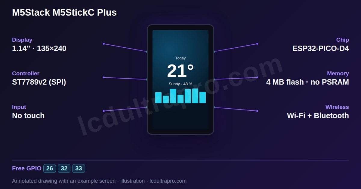
- Screen
- 1.14" · 135×240
- Chip
- ESP32
- Memory
- 4 MB flash, no PSRAM
- Input
- no touch
Key features
- 1.14-inch, 135×240, ST7789v2
- ESP32-PICO-D4, 4 MB flash
- AXP192 PMU, MPU6886 IMU, BM8563 RTC
- Microphone, buzzer, IR transmitter, red LED
- Grove port and HAT header
- 120 mAh battery
Specifications
| Manufacturer | M5Stack |
|---|---|
| Screen size | 1.14" |
| Resolution | 135×240 px |
| Colour depth | 16-bit |
| Display controller | ST7789v2 (SPI) |
| Display interface | SPI |
| Touch | None (2 buttons) |
| Microcontroller | ESP32 |
| Module | ESP32-PICO-D4 |
| CPU clock | 240 MHz |
| Internal SRAM | 520 KB |
| PSRAM | None |
| Flash | 4 MB |
| Wi-Fi | Yes |
| Bluetooth | Yes |
| Hardware variant | AXP192 PMU, MPU6886 IMU, BM8563 RTC, SPM1423 microphone, passive buzzer, IR transmitter, 120 mAh battery. G36 and G25 share a header pin; set the unused one to floating input. |
| Display | 135×240, ST7789v2: MOSI 15, CLK 13, DC 23, RST 18, CS 5 |
| I2C | SDA 21, SCL 22: IMU, PMU, RTC |
| Inputs | Button A GPIO 37, Button B GPIO 39 |
| Audio | Microphone CLK 0 / DATA 34, buzzer GPIO 2 |
| Other | IR GPIO 9, red LED GPIO 10 |
| Size | 48 × 24 × 13.5 mm, 16.9 g |
GPIO pinout
The GPIOs the board itself uses for the display, touch and on-board peripherals, as published in the manufacturer’s documentation. Pins whose function isn’t stated clearly are left out.
| GPIO | Function |
|---|---|
| GPIO 0 | Microphone clock (also on the HAT header) |
| GPIO 2 | Buzzer |
| GPIO 5 | LCD CS |
| GPIO 9 | IR transmitter |
| GPIO 10 | Red LED |
| GPIO 13 | LCD SCK |
| GPIO 15 | LCD MOSI |
| GPIO 18 | LCD reset |
| GPIO 21 | I2C SDA (IMU, PMU, RTC) |
| GPIO 22 | I2C SCL (IMU, PMU, RTC) |
| GPIO 23 | LCD DC |
| GPIO 26 | HAT header GPIO |
| GPIO 32 | Grove port (yellow) |
| GPIO 33 | Grove port (white) |
| GPIO 34 | Microphone data |
| GPIO 37 | Button A |
| GPIO 39 | Button B |
Source: github.com, docs.m5stack.com, docs.m5stack.com. Always check against your board revision before wiring.
Free GPIOs and connectors
These GPIOs are not used by the display, touch or on-board peripherals, so you can wire your own sensors, buttons or relays to them.
| Pin | Capabilities | Note |
|---|---|---|
| GPIO 26 | GPIO, PWM | On the HAT header |
| GPIO 32 | GPIO, PWM, ADC | Grove port (yellow) |
| GPIO 33 | GPIO, PWM, ADC | Grove port (white) |
- Grove port — GPIO 32, 33 · HY2.0-4P
- HAT header — GPIO 0, 26 · 8-pin female
Also G36 / G25, which share one pin
Good to know before you start
- The LCD Ultra Pro editor supports the StickC Plus2, not this Plus yet.
- No PSRAM, 4 MB flash. Keep UIs small.
- GPIO 36 and 25 share one HAT pin. Leave the unused one as a floating input.
What it is good for
- •Wearable remotes and IR controllers
- •Motion sensing and gestures
- •Tiny dashboards on a lanyard
LVGL support in LCD Ultra Pro™
This board is documented in the wiki, but it is not in the LCD Ultra Pro™ editor yet, so you can’t pick it there or export a project for it. The specs, pins and connectors on this page come from the manufacturer’s own material and are there to help you wire and configure it. See the board list for boards the editor supports today.
Arduino IDE settings
From the manufacturer's documentation (not tested by us yet)
| Board | M5StickCPlus |
|---|
Board package: M5Stack board package (Boards Manager: M5Stack)
Menu items the manufacturer doesn't mention are left at their defaults. We haven't compiled a driver for this board ourselves yet. Manufacturer's source
Frequently asked questions
What is the difference between StickC Plus and StickC Plus2?
The Plus uses an AXP192 PMU and an ESP32-PICO-D4 with 4 MB flash. The Plus2 is a later redesign with a different chip and power circuit, so check its own page.
Which pins are free on the M5StickC Plus?
GPIO 32 and 33 on the Grove port, and GPIO 26 (plus the shared 36/25 pin) on the HAT header.
Does it have a speaker?
It has a passive buzzer on GPIO 2, not a speaker.
Sources
Specifications cross-checked against the manufacturer’s documentation (last checked 2026-11-03):
More in the M5Stack family
Tools for this board
Connect sensors and parts
- 28BYJ-48 stepper
- A4988 stepper driver
- ACS712 current sensor
- ADS1115 ADC
- ADXL345 accelerometer
- AHT20
- AS5600 magnetic encoder
- BH1750
- BME280
- BME680
- BMP280
- BTS7960 motor driver
- CAN bus (SN65HVD230)
- Capacitive soil moisture
- DFPlayer Mini
- DHT22 / AM2302
- DS18B20
- DS3231 RTC
- EC11 rotary encoder
- ENS160
- HC-SR04
- HC-SR501 PIR
- HX711 load cell
- INA219
- INA226
- INMP441 microphone
- IRLZ44N MOSFET
- KY-023 joystick
- 4x4 matrix keypad
- LD2410 radar
- LDR photoresistor
- MAX31855 thermocouple
- MAX7219 LED matrix
- MAX98357A I2S amp
- MCP23017 GPIO expander
- microSD card
- MLX90614 IR thermometer
- MPU6050
- MQ-2 gas sensor
- NEO-6M GPS
- NTC thermistor 10k
- PCA9685 PWM driver
- Piezo buzzer
- Push button
- PZEM-004T
- RC522 RFID
- 5 V relay module
- RS-485 (MAX3485)
- SCD40
- SG90 servo
- SHT31 / SHT3x
- SIM800L GSM
- SSD1306 OLED
- SSR-40DA relay
- LoRa SX1276
- TB6612FNG motor driver
- TCS34725 colour sensor
- TP4056 battery charger
- TTP223 touch button
- VL53L0X
- WS2812B LED strip
- YF-S201 flow sensor
Last updated:
Adding I2C sensors to this board?See which addresses its own chips already use, and what would clash.Open the checkerSomething wrong on this page?
Tell me what you found. I check every report and fix the page.