Elecrow · ESP32-P4 · 7.0" · 1024×600
Elecrow CrowPanel Advanced 7" ESP32-P4 HMI specifications
This page collects the pinout, free GPIOs and hardware details of the CrowPanel Advanced 7" ESP32-P4. The board isn't in the LCD Ultra Pro™ editor yet, so there's no driver for it there.
Eleven free GPIOs on a header. That's rare on an ESP32 display, and it's the first thing I'd point out about the Advanced 7-inch. The 2×12 female header carries GPIO 2 to 5, 25 and 49 to 54 plus 3.3 V and 5 V, none of them claimed by the board. That's the V1.2 layout. On V1.0 and V1.1 the radio socket uses GPIO 53/54 and the header gets 27/28, so check the revision before you claim those two pins.
The display side is a 1024×600 IPS panel on two MIPI-DSI lanes. Elecrow's ESP-IDF examples use the EK79007 panel driver and a GT911 touch controller, with LCD reset on GPIO 41, touch reset on 40 and touch interrupt on 42. The backlight takes two lines: power enable on GPIO 29 and PWM on GPIO 31.
Under it runs an ESP32-P4 with 32 MB of PSRAM and 16 MB of flash, plus an ESP32-C6-MINI-1 for Wi-Fi 6 and Bluetooth 5. There's a MIPI-CSI camera connector, a microSD slot, an amplifier for a 4 Ω 3 W speaker, a PDM microphone, battery charging, three UARTs and a radio-module socket. Elecrow writes lessons for both ESP-IDF and the Arduino IDE, and both sets run on LVGL 8.3. The SquareLine Studio example is the odd one out, on LVGL 9.
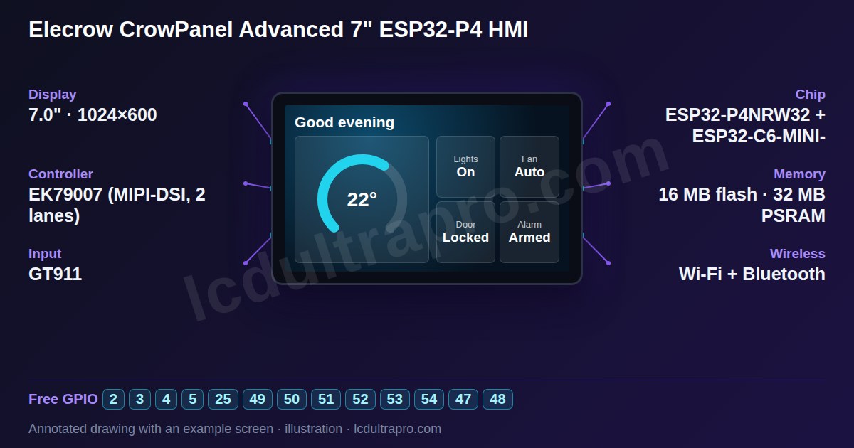
- Screen
- 7.0" · 1024×600
- Chip
- ESP32-P4
- Memory
- 16 MB flash, 32 MB PSRAM (OPI/HPI)
- Input
- capacitive touch
Key features
- 7-inch IPS, 1024×600, MIPI-DSI (2 lanes)
- GT911 capacitive touch, up to 5 points
- ESP32-P4, 32 MB PSRAM, 16 MB flash
- Wi-Fi 6 and Bluetooth 5 via ESP32-C6
- 2×12 header with 11 free GPIOs
- MIPI-CSI camera connector, microSD
Specifications
| Manufacturer | Elecrow |
|---|---|
| Screen size | 7.0" |
| Resolution | 1024×600 px |
| Colour depth | 24-bit |
| Display controller | EK79007 (MIPI-DSI, 2 lanes) |
| Display interface | MIPI-DSI |
| Touch | GT911 (capacitive, I2C, address 0x5D or 0x14) |
| Microcontroller | ESP32-P4 |
| Module | ESP32-P4NRW32 + ESP32-C6-MINI-1 (Wi-Fi 6 / Bluetooth 5 co-processor over SDIO) |
| CPU clock | 400 MHz |
| Internal SRAM | 768 KB |
| PSRAM | 32 MB (OPI/HPI) |
| Flash | 16 MB |
| Wi-Fi | Yes |
| Bluetooth | Yes |
| Hardware variant | Pin map per the Elecrow wiki for hardware V1.2. Audio: I2S speaker amplifier (4 ohm 3 W speaker, PH2.0-2P) and a PDM microphone; the wiki lists no audio codec. Backlight: power enable on GPIO 29, PWM on GPIO 31. V1.1 reversed the ESP32-C6 SDIO data lines (D0-D3 = GPIO 17-14, was 14-17) and added 4-wire SDIO. V1.2 swapped GPIO 27/28 and 53/54 between the wireless-module socket and the GPIO header. With the screen on the board draws 8-10 W, so a PC USB port alone may not be enough. |
| Display | 7-inch IPS, 1024×600, EK79007 driver over MIPI-DSI, backlight power GPIO 29, PWM GPIO 31 |
| Touch | GT911 (0x5D or 0x14), I2C GPIO 45/46, RST 40, INT 42 |
| Wireless | ESP32-C6-MINI-1 on SDIO (GPIO 14 to 19), reset on GPIO 32 |
| Audio | I2S amplifier on GPIO 21 to 23 (control 30), 4 Ω 3 W speaker, PDM mic on GPIO 24/26 |
| Ports | GPIO header (2×12), UART1 and I2C (HY2.0-4P), UART3-IN (XH2.54-4P), speakers, battery |
| Size | 180 × 105 mm, active area 155 × 87 mm |
Board layout and connectors
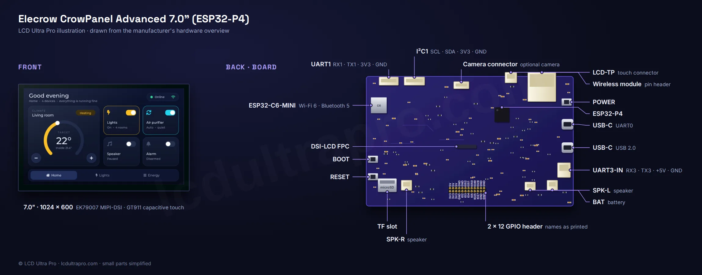
Where each connector, button and LED sits on the Elecrow CrowPanel Advanced 7-inch ESP32-P4 HMI, with the pin order next to each header where the manufacturer confirms it. We drew it from the manufacturer’s own photos and board documentation. The tiny parts are simplified.
GPIO pinout
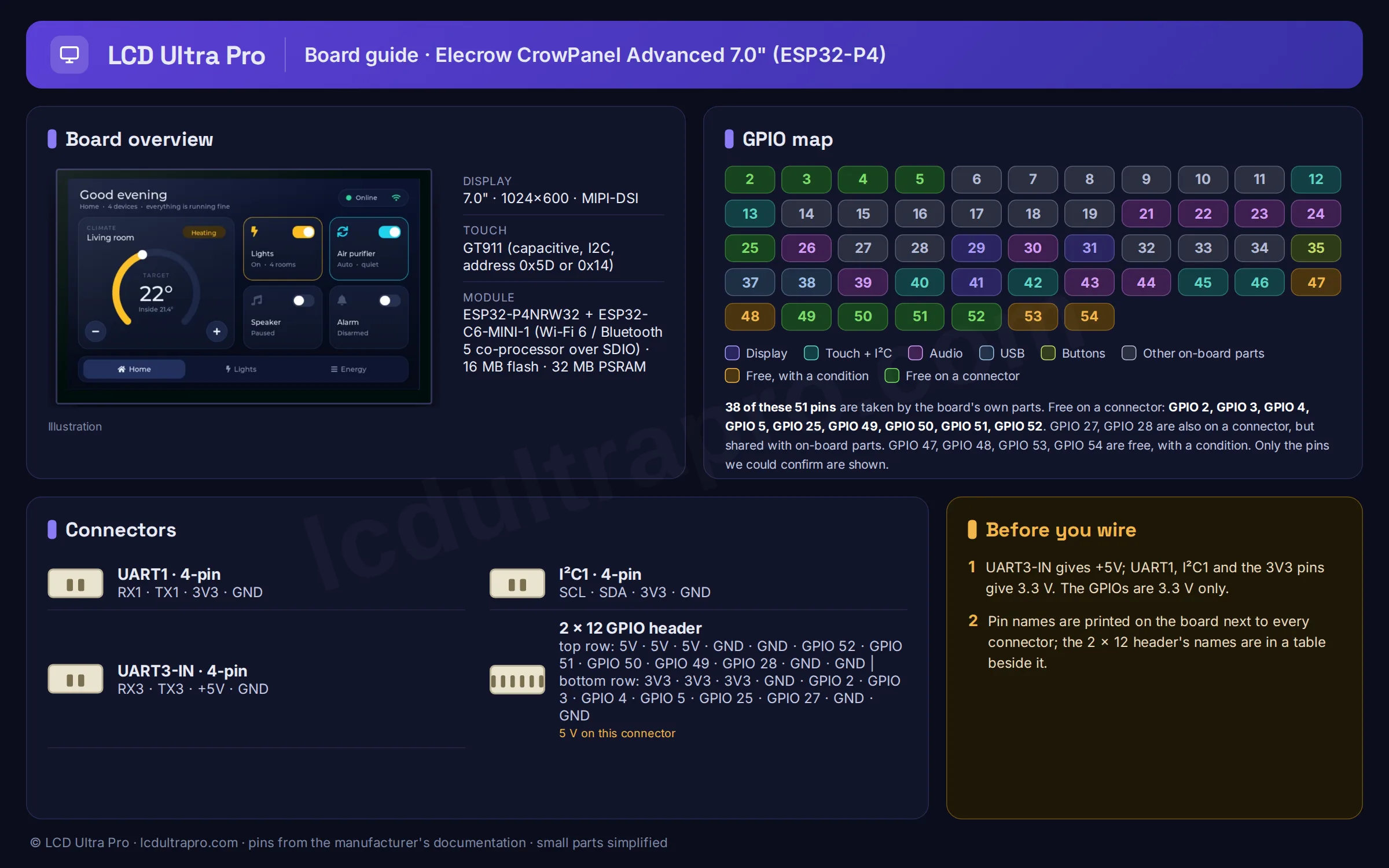
The GPIOs the board itself uses for the display, touch and on-board peripherals, as published in the manufacturer’s documentation. Pins whose function isn’t stated clearly are left out.
| GPIO | Function |
|---|---|
| GPIO 2 | GPIO header |
| GPIO 3 | GPIO header |
| GPIO 4 | GPIO header |
| GPIO 5 | GPIO header |
| GPIO 6 | Wireless module SPI MOSI |
| GPIO 7 | Wireless module SPI MISO |
| GPIO 8 | Wireless module SPI SCK |
| GPIO 9 | Wireless module: SX1262 BUSY / nRF24 IRQ |
| GPIO 10 | Wireless module: SX1262 NSS (chip select) |
| GPIO 11 | Camera reset |
| GPIO 12 | Camera I2C SDA |
| GPIO 13 | Camera I2C SCL |
| GPIO 14 | ESP32-C6 SDIO D3 (V1.1+; D0 on V1.0) |
| GPIO 15 | ESP32-C6 SDIO D2 (V1.1+; D1 on V1.0) |
| GPIO 16 | ESP32-C6 SDIO D1 (V1.1+; D2 on V1.0) |
| GPIO 17 | ESP32-C6 SDIO D0 (V1.1+; D3 on V1.0) |
| GPIO 18 | ESP32-C6 SDIO CLK |
| GPIO 19 | ESP32-C6 SDIO CMD |
| GPIO 21 | I2S LRCK (speaker amplifier) |
| GPIO 22 | I2S BCLK (speaker amplifier) |
| GPIO 23 | I2S data out (speaker amplifier) |
| GPIO 24 | PDM microphone clock |
| GPIO 25 | GPIO header |
| GPIO 26 | PDM microphone data |
| GPIO 27 | Wireless module: SX1262 IRQ / nRF24 CE (V1.2; GPIO 53 on V1.0/V1.1) |
| GPIO 28 | Wireless module: SX1262 reset / nRF24 CSN (V1.2; GPIO 54 on V1.0/V1.1) |
| GPIO 29 | Backlight power enable (LCD_BK_POWER) |
| GPIO 30 | Speaker amplifier control |
| GPIO 31 | Backlight enable (PWM) |
| GPIO 32 | ESP32-C6 enable / reset |
| GPIO 33 | UART3 RX (UART3-IN terminal) |
| GPIO 34 | UART3 TX (UART3-IN terminal) |
| GPIO 35 | BOOT button |
| GPIO 37 | UART0 TX (USB serial) |
| GPIO 38 | UART0 RX (USB serial) |
| GPIO 39 | microSD D0 |
| GPIO 40 | Touch reset |
| GPIO 41 | LCD reset |
| GPIO 42 | Touch interrupt |
| GPIO 43 | microSD CLK |
| GPIO 44 | microSD CMD |
| GPIO 45 | I2C SDA (touch, I2C port) |
| GPIO 46 | I2C SCL (touch, I2C port) |
| GPIO 47 | UART1 TX (UART1 port) |
| GPIO 48 | UART1 RX (UART1 port) |
| GPIO 49 | GPIO header |
| GPIO 50 | GPIO header |
| GPIO 51 | GPIO header |
| GPIO 52 | GPIO header |
| GPIO 53 | GPIO header |
| GPIO 54 | GPIO header |
Source: github.com, www.elecrow.com, www.elecrow.com, www.elecrow.com. Always check against your board revision before wiring.
Free GPIOs and connectors
These GPIOs are not used by the display, touch or on-board peripherals, so you can wire your own sensors, buttons or relays to them.
| Pin | Capabilities | Note |
|---|---|---|
| GPIO 2 | GPIO, PWM | On the 2 x 12 GPIO header |
| GPIO 3 | GPIO, PWM | On the 2 x 12 GPIO header |
| GPIO 4 | GPIO, PWM | On the 2 x 12 GPIO header |
| GPIO 5 | GPIO, PWM | On the 2 x 12 GPIO header |
| GPIO 25 | GPIO, PWM | On the 2 x 12 GPIO header |
| GPIO 49 | GPIO, PWM, ADC | On the 2 x 12 GPIO header |
| GPIO 50 | GPIO, PWM, ADC | On the 2 x 12 GPIO header |
| GPIO 51 | GPIO, PWM, ADC | On the 2 x 12 GPIO header |
| GPIO 52 | GPIO, PWM, ADC | On the 2 x 12 GPIO header |
| GPIO 53 | GPIO, PWM, ADC | On the 2 x 12 GPIO header (V1.2; on V1.0/V1.1 this pin goes to the wireless-module socket and GPIO 27 is on the header) |
| GPIO 54 | GPIO, PWM, ADC | On the 2 x 12 GPIO header (V1.2; on V1.0/V1.1 this pin goes to the wireless-module socket and GPIO 28 is on the header) |
| GPIO 47 | GPIO, PWM | UART1 TX on the UART1 port (HY2.0-4P) |
| GPIO 48 | GPIO, PWM | UART1 RX on the UART1 port (HY2.0-4P) |
- GPIO header — GPIO 2, 3, 4, 5, 25, 49, 50, 51, 52, 53, 54 · 2 x 12-pin female
Also carries 3.3 V, 5 V and GND. Pin list is for V1.2; V1.0/V1.1 have GPIO 27/28 here instead of 53/54
- UART1 port — GPIO 48, 47 (RX, TX) · HY2.0-4P
3.3 V output, 1 A max
- I2C port — GPIO 46, 45 (SCL, SDA) · HY2.0-4P
Level-shifted; same bus as the GT911 touch. 3.3 V output, 1 A max
- UART3-IN terminal — GPIO 34, 33 (TX, RX) · XH2.54-4P
Level-shifted, also a 5 V (+/-5 %, 2 A max) power input
- Wireless module header — GPIO 6, 7, 8, 9, 10, 27, 28 · 2 x 7-pin female
SPI (SCK 8, MISO 7, MOSI 6) plus SX1262 or nRF24 control lines. Pin list is for V1.2; V1.0/V1.1 use GPIO 53/54 instead of 27/28. 3.3 V, 1 A max
Good to know before you start
- The LCD Ultra Pro editor doesn't cover this board yet. There's no Arduino export for it from us.
- Not the same product as the CrowPanel Advance 7.0 ESP32-S3, which is 800×480.
- With the screen on it pulls 8 to 10 W. A single PC USB port often can't keep up and the screen goes dark, so plug in the second USB port too, or feed 5 V into UART3-IN.
- The camera connector shares nothing with the header, so camera and GPIO projects can coexist.
- The Arduino lessons ship their own copies of LVGL 8.3.11 and the ESP32_Display_Panel library. Use those. The Library Manager offers LVGL 9, which the sketches weren't written for.
What it is good for
- •Home Assistant panels with a camera doorbell view
- •Machine HMIs that need plenty of GPIO
- •Smooth LVGL interfaces at 1024×600
LVGL support in LCD Ultra Pro™
This board is documented in the wiki, but it is not in the LCD Ultra Pro™ editor yet, so you can’t pick it there or export a project for it. The specs, pins and connectors on this page come from the manufacturer’s own material and are there to help you wire and configure it. See the board list for boards the editor supports today.
Arduino IDE settings
From the manufacturer's documentation (not tested by us yet)
| Board | ESP32P4 Dev Module |
|---|---|
| Flash Frequency | 80MHz |
| Flash Mode | QIO |
| Flash Size | 16MB (128Mb) |
| Partition Scheme | 16M Flash (3MB APP/9.9MB FATFS) |
| PSRAM | Enabled |
| Upload Mode | UART0 / Hardware CDC |
| USB Mode | Hardware CDC and JTAG |
Board package: esp32 by Espressif Systems 3.3.3 (or the version the course package names)
Menu items the manufacturer doesn't mention are left at their defaults. We haven't compiled a driver for this board ourselves yet. Manufacturer's source
Frequently asked questions
Which GPIOs are free on the CrowPanel Advanced 7-inch?
On V1.2 boards: GPIO 2, 3, 4, 5, 25 and 49 to 54 on the 2×12 header, plus GPIO 47/48 on the UART1 port. On V1.0 and V1.1, GPIO 27 and 28 take the place of 53 and 54.
Which display driver do the examples use?
Elecrow's ESP-IDF projects pull in the EK79007 MIPI-DSI panel driver and the GT911 touch driver.
Can I run Arduino code on it?
Yes. Elecrow's GitHub repository has Arduino IDE lessons for hardware V1.0 and V1.1, up to an LVGL light-control screen, and the wiki links a separate course for V1.2. The sketches use LVGL 8.3.11 with the ESP32_Display_Panel library.
Sources
Specifications cross-checked against the manufacturer’s documentation (last checked 2026-11-04):
- https://github.com/Elecrow-RD/CrowPanel-Advanced-7inch-ESP32-P4-HMI-AI-Display-1024x600-IPS-Touch-Screen
- https://www.elecrow.com/crowpanel-advanced-7inch-esp32-p4-hmi-ai-display-1024x600-ips-touch-screen-with-wifi-6-compatible-with-arduino-lvgl-micropython.html
- https://www.elecrow.com/wiki/CrowPanel_Advanced_7inch_ESP32-P4_HMI_AI_Display_1024x600_IPS_Touch_Screen_with_WiFi6_Compatible_with_ArduinoLVGL.html
- https://www.elecrow.com/wiki/P4_Arduino_01_Print_Hello_World.html
More in the Elecrow CrowPanel family
- Elecrow CrowPanel 1.28" ESP32-S3 Round Rotary Display
- Elecrow CrowPanel ESP32-C3 1.28" Round Display
- Elecrow CrowPanel 1.46" ESP32-S3 Round Rotary Display
- Elecrow CrowPanel 2.01" ESP32-S3 Watch Display
- Elecrow CrowPanel 2.1" ESP32-S3 Round Rotary Display
- Elecrow CrowPanel Advance 2.4" ESP32-S3 HMI
- Elecrow CrowPanel ESP32 HMI 2.4"
- Elecrow CrowPanel Advance 2.8" ESP32-S3 HMI
- Elecrow CrowPanel ESP32 HMI 2.8"
- Elecrow CrowPanel Advance 3.5" ESP32-S3 HMI
- Elecrow CrowPanel ESP32 HMI 3.5"
- Elecrow ESP Terminal 3.5" 16-bit Parallel
- Elecrow ESP Terminal 3.5" SPI with Camera
- Elecrow CrowPanel Advance 4.3" ESP32-S3 HMI
- Elecrow CrowPanel ESP32-S3 HMI 4.3"
- Elecrow CrowPanel Advance 5.0" ESP32-S3 HMI
- Elecrow CrowPanel Advanced 5" ESP32-P4 HMI
- Elecrow CrowPanel ESP32-S3 HMI 5.0"
- Elecrow CrowPanel Advance 7.0" ESP32-S3 HMI
- Elecrow CrowPanel ESP32-S3 HMI 7.0"
- Elecrow CrowPanel Advanced 9" ESP32-P4 HMI
- Elecrow CrowPanel Advanced 10.1" ESP32-P4 HMI
Tools for this board
- CrowPanel Advanced 7" ESP32-P4 Arduino IDE settings
- CrowPanel Advanced 7" ESP32-P4 pin planner
- CrowPanel Advanced 7" ESP32-P4 side-by-side comparison
- CrowPanel Advanced 7" ESP32-P4 LVGL memory estimate
- CrowPanel Advanced 7" ESP32-P4 I2C address check
- Other ESP32 boards with the EK79007
- Find similar ESP32 display boards
Connect sensors and parts
- 28BYJ-48 stepper
- A4988 stepper driver
- ACS712 current sensor
- ADS1115 ADC
- ADXL345 accelerometer
- AHT20
- AS5600 magnetic encoder
- BH1750
- BME280
- BME680
- BMP280
- BTS7960 motor driver
- CAN bus (SN65HVD230)
- Capacitive soil moisture
- DFPlayer Mini
- DHT22 / AM2302
- DS18B20
- DS3231 RTC
- EC11 rotary encoder
- ENS160
- HC-SR04
- HC-SR501 PIR
- HX711 load cell
- INA219
- INA226
- INMP441 microphone
- IRLZ44N MOSFET
- KY-023 joystick
- 4x4 matrix keypad
- LD2410 radar
- LDR photoresistor
- MAX31855 thermocouple
- MAX7219 LED matrix
- MAX98357A I2S amp
- MCP23017 GPIO expander
- microSD card
- MLX90614 IR thermometer
- MPU6050
- MQ-2 gas sensor
- NEO-6M GPS
- NTC thermistor 10k
- PCA9685 PWM driver
- Piezo buzzer
- Push button
- PZEM-004T
- RC522 RFID
- 5 V relay module
- RS-485 (MAX3485)
- SCD40
- SG90 servo
- SHT31 / SHT3x
- SIM800L GSM
- SSD1306 OLED
- SSR-40DA relay
- LoRa SX1276
- TB6612FNG motor driver
- TCS34725 colour sensor
- TP4056 battery charger
- TTP223 touch button
- VL53L0X
- WS2812B LED strip
- YF-S201 flow sensor
Last updated:
Adding I2C sensors to this board?See which addresses its own chips already use, and what would clash.Open the checkerSomething wrong on this page?
Tell me what you found. I check every report and fix the page.